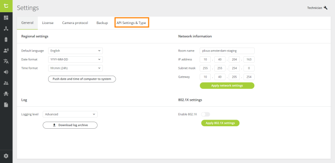
Settings
Use the Settings page to configure general system settings such as the IP address and the date/time format. To access the Settings page, click the icon ![]() in the menu on the left. The settings are divided in four groups over four different tabs:
in the menu on the left. The settings are divided in four groups over four different tabs:
- General
- Network
- License
- Camera protocol
- Backup
- API Settings & Type
General
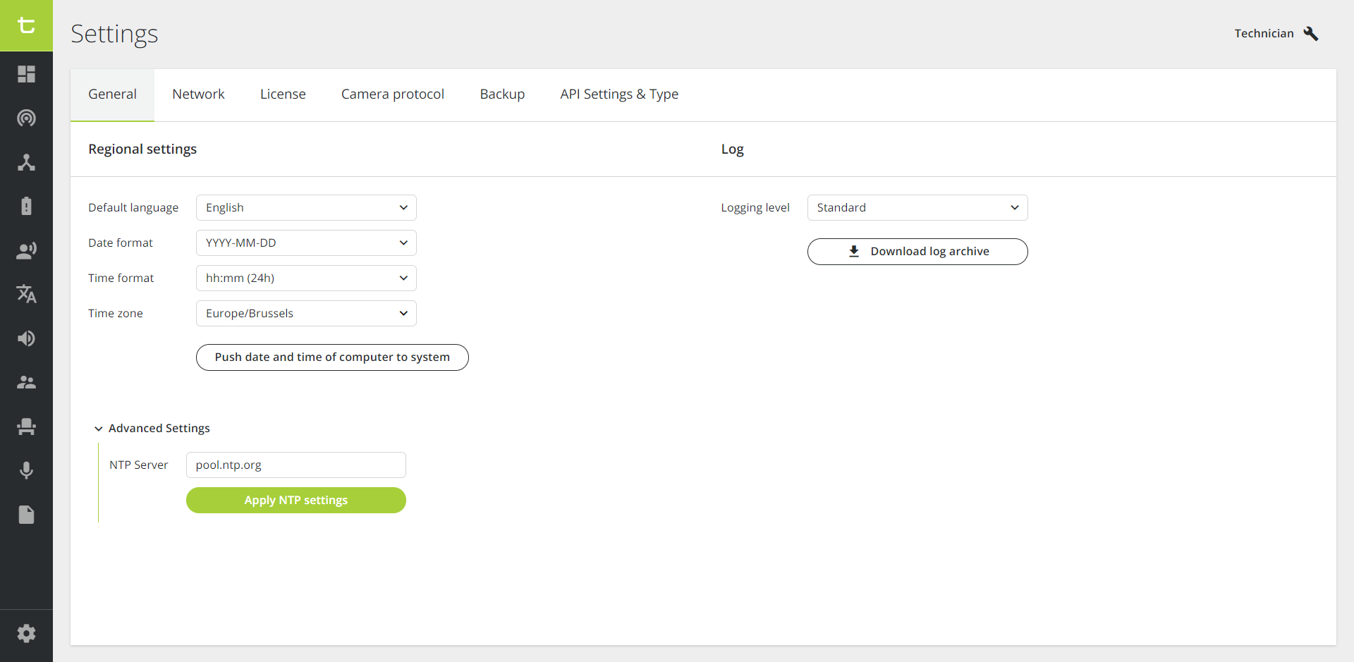
Figure 1-1: General tab of the Settings
Regional settings
In the Regional settings, you can set the default language, the date and time format, as well as the time zone, using the provided dropdown boxes. The time zone has to be filled in to have a correct display of the time on your system (e.g. If you enter "Bru", the "Europe/Brussels" time zone will automatically appear).
When clicking on the button "Push date and time of computer to system", you'll synchronize the time and date of the PC with the system.
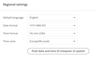
Figure 1-2: Overview of the Regional settings
Advanced settings
In the Advanced Settings section, you can add an NTP server to synchronize the system clock (visible on the display screen of the units) to an NTP time server on the Internet or a local network.
Click on the button Apply NTP settings to implement the changes. The settings will be applied immediately, so no reboot is necessary. It is however possible that when the Apply button is pressed, the connection to the web interface is lost.
The following information need to be taken into account:
-
It is possible to fill in either an IP address or a domain name in the NTP server field. If a domain name is used, the IP address of a reachable domain name should be configured via the Network tab (DNS Primary and DNS Secondary).
-
No NTP service is used when an empty string is configured in the NTP server field. In that case, the time must be pushed manually by clicking the button Push date and time of computer to system .
-
If you click the button Push date and time of computer to system although an NTP server has been configured and is reachable, the time from the NTP service will prevail.
-
About 10 seconds are necessary to update the system time to a newly implemented NTP server.
-
When DHCP is enabled (see Network section here-below), the NTP server cannot be configured manually and the NTP server fields and button are grayed out. In that case, the NTP server can be communicated as one of the optional DHCP configuration parameters. To make sure the system works properly, an NTP server must be present on the network and the DHCP server configured to include the NTP server in the optional parameters. If DHCP is enabled but there is no NTP server on the network, it is still possible to click the button Push date and time of computer to system.
The Central Unit will try to reach the DHCP server three times. This process takes about 10 seconds. Unless another device is already using the default IP address, a fallback to the default factory address will be implemented after 15 to 20 seconds. Otherwise, no IP address will be configured. A DHCP retry will be done in the background after 20 seconds even if the fallback was successful.
Log
You can change the level that the system will put in the log files. This can be the standard level, or a more detailed logging.
Network
Network information
.PNG)
Figure 1-3: Network tab of the Settings
The following network settings are available:
- Room name: name you want to give to your room.
- Enable DHCP: when enabled, all network fields below are grayed outand cannot be entered manually. In that case, make sure the DHCP server has been configured to include the NTP server in the optional parameters. If DHCP is enabled but no NTP server has been defined on the network, it will still be possible to push the local time from the computer in the General tab of the Settings window. See previous section Advanced Settings for more information.
- IP address: IP address to access the Plixus engine. The default value is 192.168.0.100. The default IP for the Confidea G4 WAP is 192.168.0.110. When you change the IP address, you need to restart the engine to complete the action.
- Subnet mask: default subnet is 255.255.255.0.
- Gateway: access point to another network.
- DNS Primary / DNS Secondary: these fields are required for the NTP server when a domain name is used.
When you change the network settings, click Apply network settings to validate the changes.
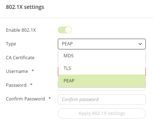
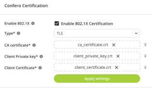
802.1X Settings
802.1X is an IEEE standard for Port-Based Network Access Protocol (PNAC). It is a highly secure network authentication protocol that allows the server to check the user's credentials and/or certificates before granting or blocking their access to the network.
The 802.1X protocol applies to Plixus LAN and WAP G4 LAN ports. Plixus wired devices do not support the 802.1X protocol.
Three types of authentication are possible:
|
Authentication Type |
Authentication Credentials |
Level of Security |
|---|---|---|
| MD5 |
Username + Password |
LOW |
|
TLS |
CA Certificate + Client Private Key + Client Certificate |
HIGH |
|
PEAP |
CA Certificate + Username + Password |
MEDIUM |
Activating the 802.1X Protocol
To activate the 802.1X protocol, process as follows:
-
Move the cursor on the right side to activate the 802.1X settings.
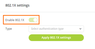
-
Select the desired authentication type.
-
Enter the credentials and upload the certificates (if applicable).
-
Click on the Apply 802.1X settings button. You then need to restart the system for the changes to be taken into account.
Renewing Certificates
When a certificate is about to expire, a notification will appear in an orange bar both on top of the dashboard and in the General Settings tab 30 days before the expiration date.

The bar will turn red 7 days before the expiration date.

A pop-up window will also show 7 days before the expiration date. Upload a new certificate as indicated in the section here-above.
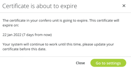
The Operator will also receive a notification when a certificate is about to expire and will be advised to refer to the Technician. 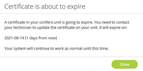
License
On the License tab, you can upload a new license or see the license information when you click one of the licenses.
.PNG)
Figure 1-4: License page
Camera protocol
The Camera protocol is disabled by default. When you enable the camera protocol, you can configure the following parameters:
- Camera protocol: select the protocol you want to use. Three protocols are available: TLVCAM 1,TLVCAM 2 and T-CAM. These are the most commonly used camera protocols that are also provided with CoCon. For more information on camera protocols, see Camera Protocol Explained in the next section. You can only choose one at a time.
- Network protocol: Choose either TCP/IP or UDP.
- Port: This is the port on the client where the camera protocol is either sent to (UDP) or where the third party client has to listen to on the Confero engine (TCP)
- IP address: When you select UDP, you need to specify the IP address of the destination (third-party).
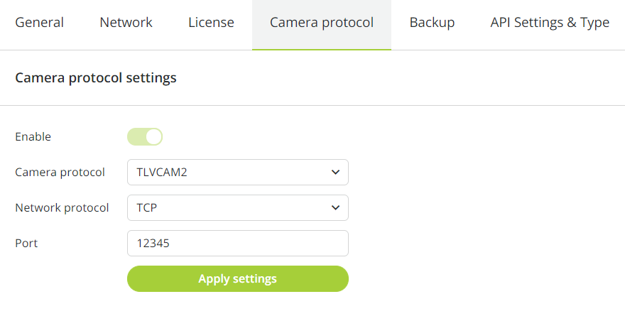
Figure 1-5: How to configure camera protocols
Camera protocols explained
When UDP is not selected, every call needs an acknowledgement. If no acknowledgement is sent back, the system tries to send the call up to 3 times. An acknowledgement is 1 byte long and contains hexadecimal value 0x06.
Commands for TLVCAM1 protocol
A call is made up of four distinct parts and looks like the following: {STX}{Body}{CRC}{ETX}.
STX
STX indicates the start of the command protocol. You can recognize STX because it appears as a percentage sign (%) in the command.
Body
The body is the second part of the protocol. The body itself consists of several parts as well. This is a letter (capitol or small) followed by the microphone number. The microphone number always contains four digits. For example, seat 1 will appear as 0001 in the protocol, seat 2 as 0002, and so on.
- P/p:
- When a chairperson device activates, a capital P is used. The P is followed by the number of the microphone.
- When a chairperson deactivates their microphone, a small p is used. The p is followed by the number of the microphone.
- M/m:
- When a delegate device activates, a capital M is used. The M is followed by the number of the microphone.
- When a delegate deactivates their microphone, a small m is used. The m is followed by the number of the microphone.
- R: When the last active microphone is turned off, a ‘reset’ command is sent. This command starts with a capital R. An example is: (%)R(0052)
- S:Every 5 seconds, a synchronized command is sent. This command starts with a capital S and contains all active microphones. The microphones are in order of activation. The first activated microphone is the first number in this part of the protocol. For example (%)S00250001(01DB) means that the first microphone to be activated was microphone 25. Microphone 1 was the second microphone to be activated. If no microphone is active, the synchronization will send S0000 as {Body} in the protocol: (%)S0000(0113).
CRC
CRC is the third part of the command protocol. It is an extra check to make sure that nothing went wrong during the transmission.
The CRC is the 16 bit hexadecimal sum of all ASCII characters in {Body}. For example, {Body} can equal S00250001. CRC will then be : 0x53+0x30+0x30+0x32+0x35+0x30+0x30+0x30+0x31 = 0x01DB
As a result, the command will be as follows: (%S00250001)01DB.
ETX
ETX indicates the end of the command protocol. The ETX is a Carriage Return (CR). The hexadecimal presentation of ETX is 0x0D.
Examples of TLVCAM1 command protocols
- If the chairman microphone is activated, and the chairman microphone is number ‘0001’, then the following message is sent: %P00010111<CR>
- When the chairman microphone is deactivated, then the following message is sent: %p00010131<CR>
- If a delegate microphone is activated, and that delegate microphone is number ‘0003’, then the following message is sent: %M00030110<CR>
- When the delegate microphone is deactivated, then the following message is sent: %m00030130<CR>
- Suppose now that the delegate microphone with number ‘0003’ is active. On a synchronization check, the synchronization message will look like this: %S00030116<CR>
- Suppose now that the delegate microphones with number ‘0002’ and ‘0004’ are also active. On a synchronization check, the synchronization message will look like this: %000300020004029C<CR>
- When no microphones are active, then the following synchronization will be received: %000300020004029C<CR>
- When the camera control system should reset itself to its start position, then the following message will be received: %R0052
- When all microphones are deactivated simultaneously, then the following message is received: %V00000116
Commands for TLVCAM2 protocol
A call is made up of three distinct parts and looks like the following: {STX}{Body}{ETX}.
STX
STX indicates the start of the command protocol. You can recognize STX because it appears as a dollar sign ($) or an ampersand sign (&) in the command.
Body
The body is the second part of the protocol. The body itself consists of several parts as well. This is a digit (1, 2 or 3) followed by the microphone number. The microphone number always contains four digits. For example, seat 1 will appear as 0001 in the protocol, seat 2 as 0002, and so on.
- 1: The microphone of the chairman or a delegate is activated. 1 is followed by the seat number of the microphone. E.g.: ($)10001(<CR><LF>).
- 2: The microphone of the chairman or a delegate is deactivated. 2 is followed by the seat number of the microphone. E.g.: ($)20001<CR><LF>).
- 3: All active microphones are deactivated. 3 is followed by number 0000. E.g.: (&)30000(<CR><LF>).
ETX
ETX indicates the end of the command protocol. The ETX is an Carriage Return (CR) followed by an Line Feed (LF). The hexadecimal presentation of CR is 0x0D and the hexadecimal presentation of the LF is 0x0A.
Examples of TLVCAM2 command protocols
- If the chairman microphone is activated, and the chairman microphone is number ‘0001’, then the following message is sent: $10001<CR><LF>.
- When the chairman microphone is deactivated, then the following message is sent: $20001<CR><LF>.
- If a delegate microphone is activated, and the delegate microphone is number '0003', then the following message is sent: $10003<CR><LF>.
- When the delegate microphone is deactivated, then the following message is sent: $20003<CR><LF>.
- When all microphones are deactivated , then the following message is received: &30000<CR><LF>.
Commands for T-CAM protocol
Once the network protocol has been defined (UDP or TCP, refer to the beginning of this section), the camera protocol works as follows:
When there is a change in the state of the microphone, a UDP/TCP data package is sent to the camera. The package is in JSON format and has the following structure: {"UID": seat_number, "status": status_number}.
- seat_number: seat number of the microphone.
- status_number: satus of the microphone. There are 2 possible status:
- 0: The microphone is deactivated
- 1: The microphone is activated
In case of multiple calls to turn off microphones, the activation order applies based on the "first in, first out" principle. For example, the call for the first microphone on will be sent as the first microphone off.
Examples of T-CAM command protocols:
- If the delegate microphone is activated, and the delegate microphone is number 7, then the following message is sent: {"UID": 7, "status": 1}.
- If the delegate microphone is deactivated, then the following message is sent: {"UID": 7, "status": 0}.
- If delegate microphones number 2, 4 and 7 are deactivated simultaneously while they were initially activated in order 4, 7 and 2, then the following messages are sent: {"UID": 4, "status": 0}, {"UID": 7, "status": 0} and {"UID": 2, "status": 0}.
Backup
On the Backup tab, you can import and export configurations. Click the respective buttons to perform these actions.
The exported configuration contains the following information:
-
Dynamics processing settings
-
Audio routing settings
-
Interpretation settings
.png)
Figure 1-6: Import and export Backup files
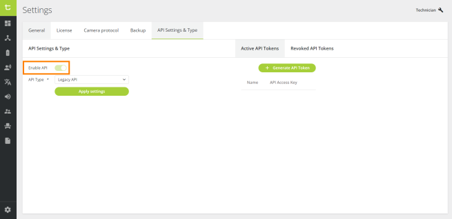
API Settings & Type
The Confero 360 API was designed to create custom solutions and integrate with your own API. With the Confero 360 Customer REST API, you can perform two types of actions:
-
Publication of events occurring in the meeting room
-
External control of the meeting room
The technology used for the API is REST (Representational State Transfer) with JSON (JavaScript Object Notation).
To activate the API, click on the API Settings & Type tab and enable the API by moving the cursor on the right side.
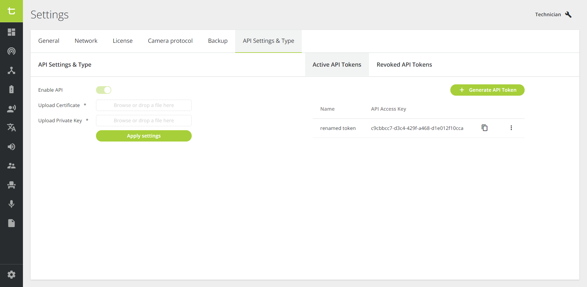
Figure 1-7: Enable API
API Options
Legacy API 
The Legacy API is deprecated and won't be maintained in the future. However, you can still contact Televic Support for more information.
Secured API (recommended) 
The Secured API has encrypted communication via HTTPS, ensured via a CA certificate (see section here-after for more information). Authentication to the API is allowed via tokens to prevent other people who know the API from executing calls. Tokens have to be added into the header of the API, otherwise the calls will not be executed.
The system hosts a Swagger file that contains the latest information about how to set up and use the API, as well as all existing API calls. It is located here: <ip-address>/openapi
CA Certificates (Secured API)
The communication is encrypted via HTTPS in order to guarantee confidentiality, authenticity and privacy of the user. To get proper encryption, a CA certificate must be created, signed and uploaded.
A CA certificate is issued by a trusted third-party called "Certificate Authority" after they verify certain information about the company requesting the certificate.
If a certificate is uploaded, the communication is secure (HTTPS) and the port number is 9443. If there's no certificate, the communication is insecure (HTTP) and the port number is 9080. For enhanced security reasons, it is then highly recommended that you create and upload your own certificate. The process is dependent on the programming language and/or framework used and is out of the scope of this document.
The creation, upload and renewal of certificates are the responsibility of the client ! Keep in mind that uploading a certificate on the Central Unit but failing to validate it on the Client's side is not secure.
The following demo is for testing purposes only. Cooperation with your IT department is required to sign certificates and align with security policies.
For more information about certificates, refer to the following pages:
Installing OpenSSL
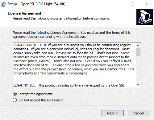
OpenSSL is pre-installed on Linux® but has to be installed on Windows®.
-
Go to https://slproweb.com/products/Win32OpenSSL.html and download Openssl for Windows®. You can select the light version, it should be an ".exe" file.
-
Accept the License Agreement.
-
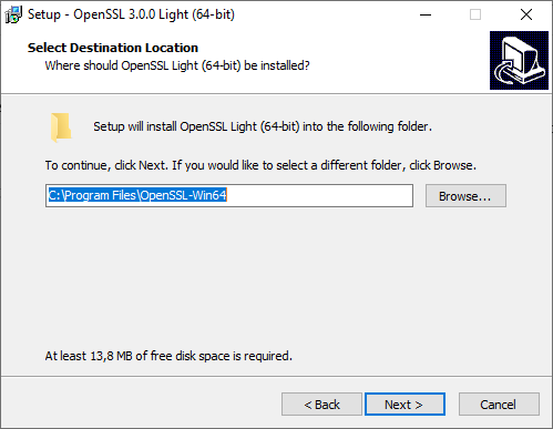
Keep the default location.
-
Select Next.
-
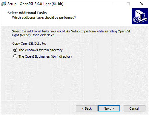
Choose The Windows system directory.
-
Click Install.
-
Click Finish.
-
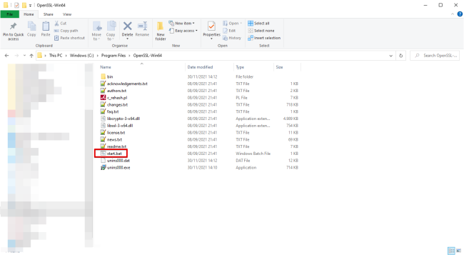
Start OpenSSL: go to the location of the installed program (by default: C:\Program Files\OpenSSL-Win64).
Creating and Signing Certificates
For testing purposes, it is possible to create a Certificate Authority. If your organization requires you to use the company's CA, please skip this step and go to Creating a Certificate Request.
Creating a CA Certificate
The commands below are in the simplest form. OpenSSL offers more options, please consult the manual for more information.
Make sure to align with your IT department on the security policies for deployment.
-
Generate a CA private key:
openssl genrsa -out server.key 2048
server.key is a private key for the Conference Controller. For security reasons, do not share this key.
-
Generate a CA root certificate. Fill in the questions asked according to your organization:
openssl req -new -x509 -days 365 -key ca.key -out ca.cert.pem
Creating a Certificate Request
-
Generate a server key:
openssl genrsa -out server.key 4096
Adjust the file server_req as the above command will prompt for information to be included in the certificate. Enter . (period) to leave the field blank. The value of Common Name (or CN) should be the IP address or DNS of the Conference Controller, that must be known in this step.
-
Generate a certificate request:
openssl req -new -key server.key -out server.csr -config server_req.cfg
Signing the Certificate Request:
-
Now the server.csr certificate must be submitted for signing by the CA. If you use your company's CA, you need to send the file to the person in charge. If you created your own CA, enter:
openssl x509 -req -days 365 -in server.csr -CA ca.cert.pem -CAkey ca.key -CAcreateserial -out server.crt -extensions req_ext -extfile server_req.cfg
The server.key file should not be sent!
-
The received certificate can be viewed with the following command in OpenSSL:
openssl x509 -text -in server.crt -noout
Installing the Root Certificate Authority
Browsers might display errors when an organization uses certificate authorities to issue certificates. It is therefore necessary to configure the browsers so that the CA certificates are recognized.
The configuration is specific for every browser / operating system. Visit the websites below for more information on browser configuration:
-
Mozilla Firefox : https://support.mozilla.org/en-US/kb/setting-certificate-authorities-firefox
-
Google Chrome: https://support.google.com/chrome/a/answer/6342302?hl=en
-
Microsoft Edge: https://computersluggish.com/windows-tutorials/software-apps/how-to-add-a-certificate-in-microsoft-edge/
When the configuration is finished, shut down your browser completely (all processes) and restart it.
Installing the Certificates
-
Log in to the Confero platform as Technician:
-
Click on the Settings icon
 in the menu on the left. The Settings page opens:
-
Click on the tab API Settings & Type:
-
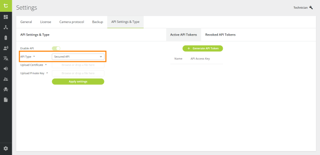
You now have access to the Confero 360 API settings. Enable the API:
-
In API Type, in case of multiple choices, select Secured API:
-
In Upload Certificate, click on Browse or drop a file here to upload a certificate from your computer, or drag and drop a file in this field:
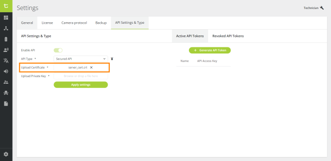
-
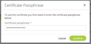
[Optional] If your certificate is password-protected, a pop-up window opens. Enter the certificate's password and click Confirm to validate:
-
In Upload Private Key, click Browse or drop a file here to upload a private key file from your computer (".pem" extension), or drag and drop a file in this field:
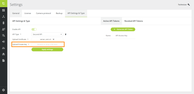
Both a certificate and private key are required for the access point to work. The private key should never be shared with anyone.
The server certificate and key file are distributed separately in this demo. They might come packed together in one file, in which case you will need to drag the same file twice in the certificate and the key drag&drop fields.
-
Click on the Apply settings button to implement the API settings.
-
After uploading the new certificate, it is recommended to reboot the Conference Controller.
Renewing a Certificate
When a certificate is about to expire, a warning message will appear on the Technician dashboard as well as the API Settings of the platform so that you can renew it on time.
Testing the Certificates
-
Prior to the testing process, make sure that the API has been enabled, that the certificates have been uploaded and that the Conference Controller has been rebooted.
-
For testing whether the certificates are properly installed, check with a random https GET method, e.g.:
https://192.168.0.110:9443/api/discussion/settings
If you're not using the default IP, replace it with the correct one.
-
The response received should be "No token received". This response is normal as a web browser does not send a token.
In case you get a security error, the openapi website will not work. Check the details of the error to get a hint of what is going wrong.
Ex-Factory and reset
The ex-factory startup behaves as follows:
-
DHCP is disabled
-
A static configuration is applied with the "legacy" IP address (192.168.0.110 for the WAP and 192.168.0.100 for the Central Unit)
A short push of 5 seconds resets all the settings to default:
-
Network settings (IP, subnetmask, default GW, room name, DHCP disabled)
-
802.1X settings (this will be turned off and all certificates will be removed)
-
WAP certificates will also be removed (802.1X certificates and API certificates)